

LED Tube
2023-07-25
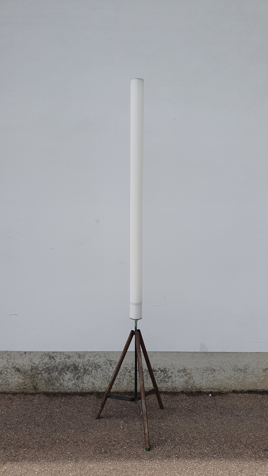
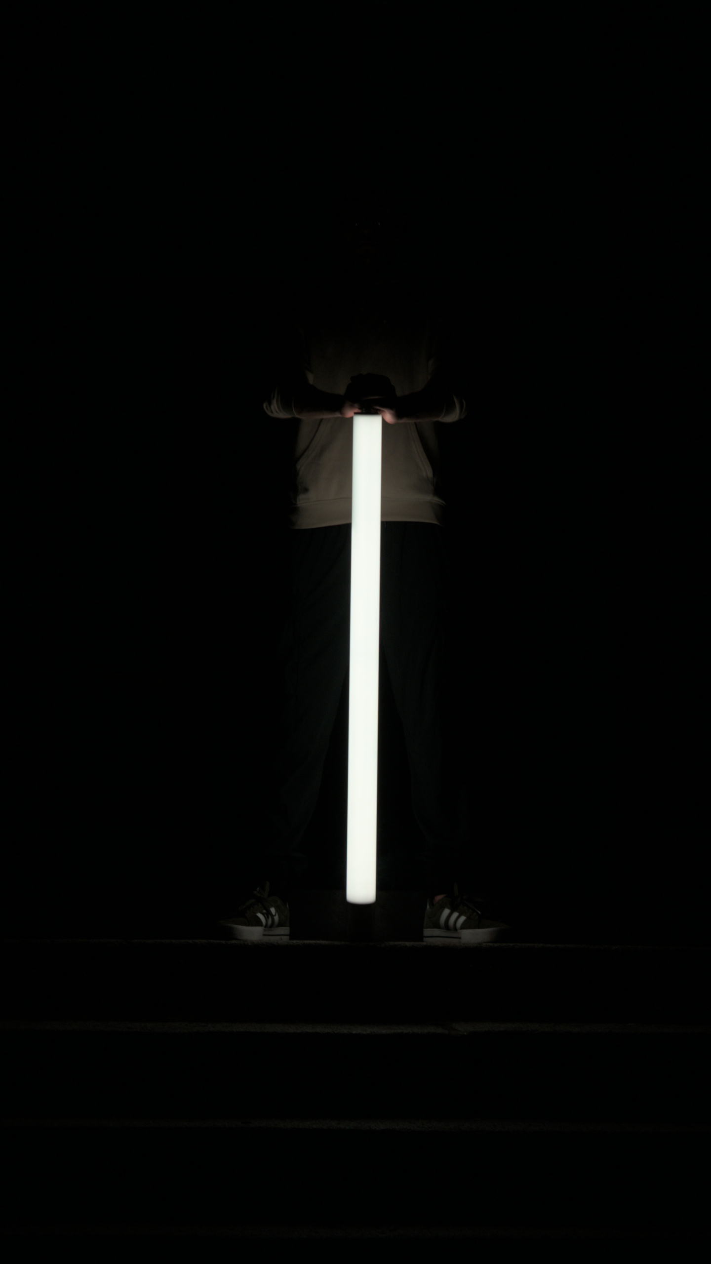
One day I stumbled across the Astera Titan Tube which is a LED-Tube that can be used to illuminate a scene during a photo shoot. I really liked them and taught I could make my own one.
The design and assembly took quite a while, which is why I’m dividing the post into individual sections.
Hardware
Something commercial products mostly can’t do but my LED tube should be capable of is 360° all around illumination. This requires the battery to be in the core of the tube and the LED’s all around. My local hardware store had some round steel tubes with a 22mm outer diameter, on which six LED-strips next to each other fit perfectly.

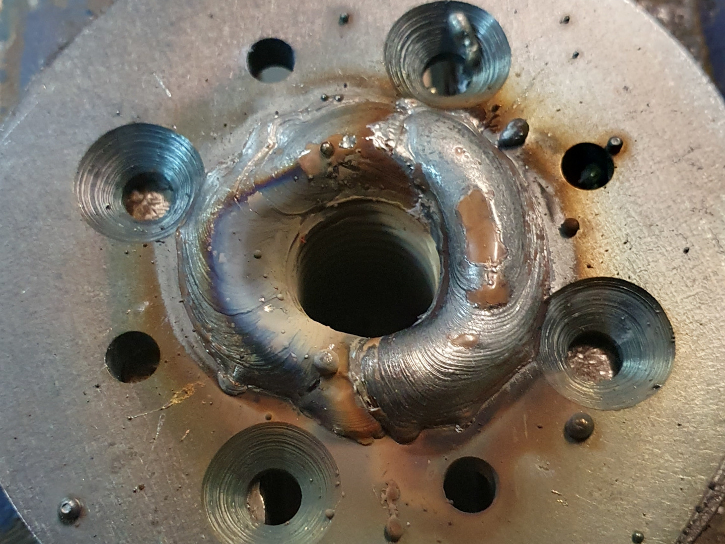
The lights needs a diffuser to shine evenly. For that I used white Plexiglas®. To keep the diffuser centered, I had a few metal washers made by Blexon and welded them to the tube. First I had a very complicated design with lots of different parts, but I got it down to only two, which made the parts way cheaper.

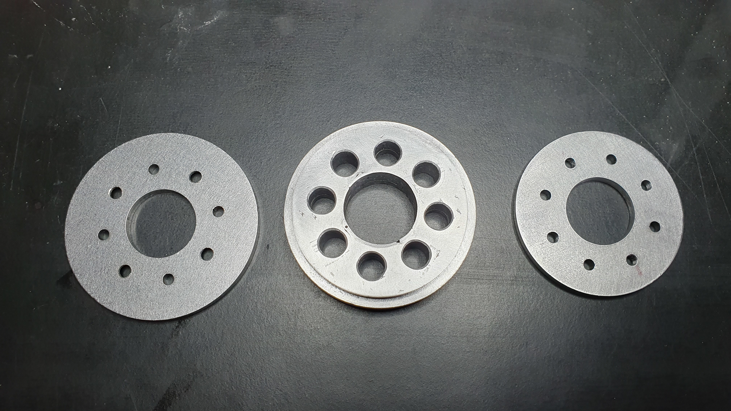
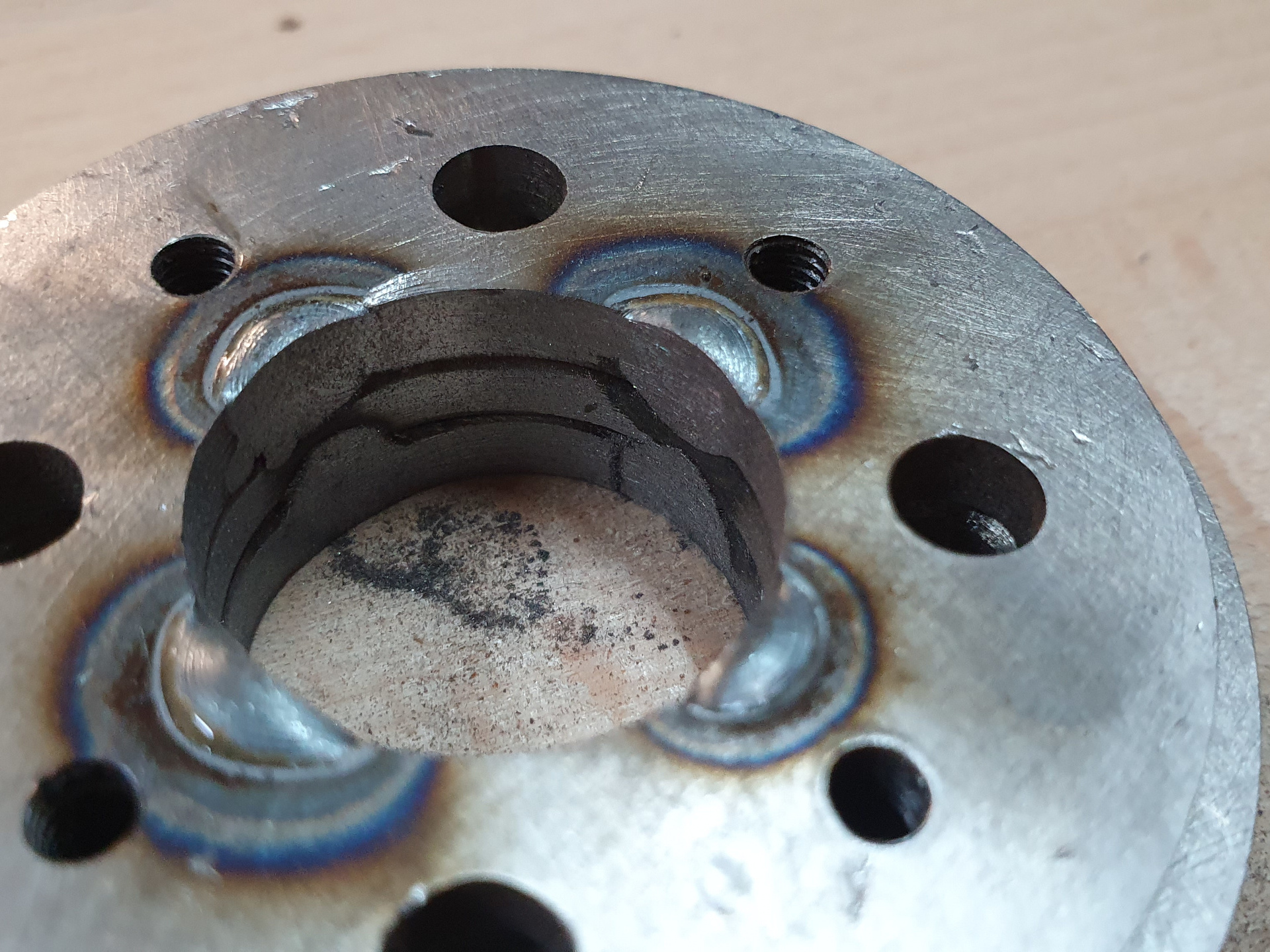
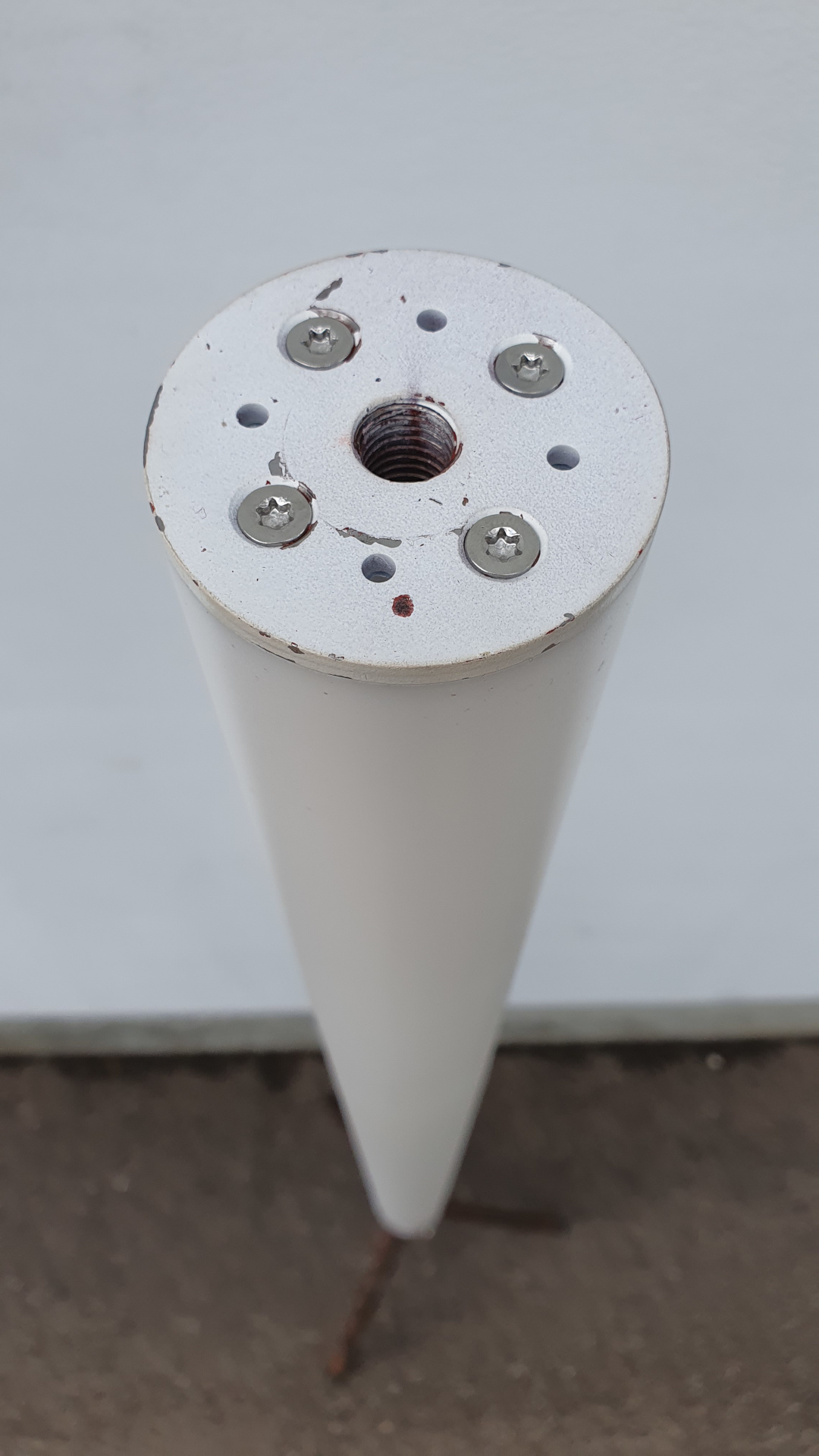

The tripod visible on the last page was made at the very end of the project and is made up of just a couple of steel tubes and a M12 threaded rod.
Electronics
LED's
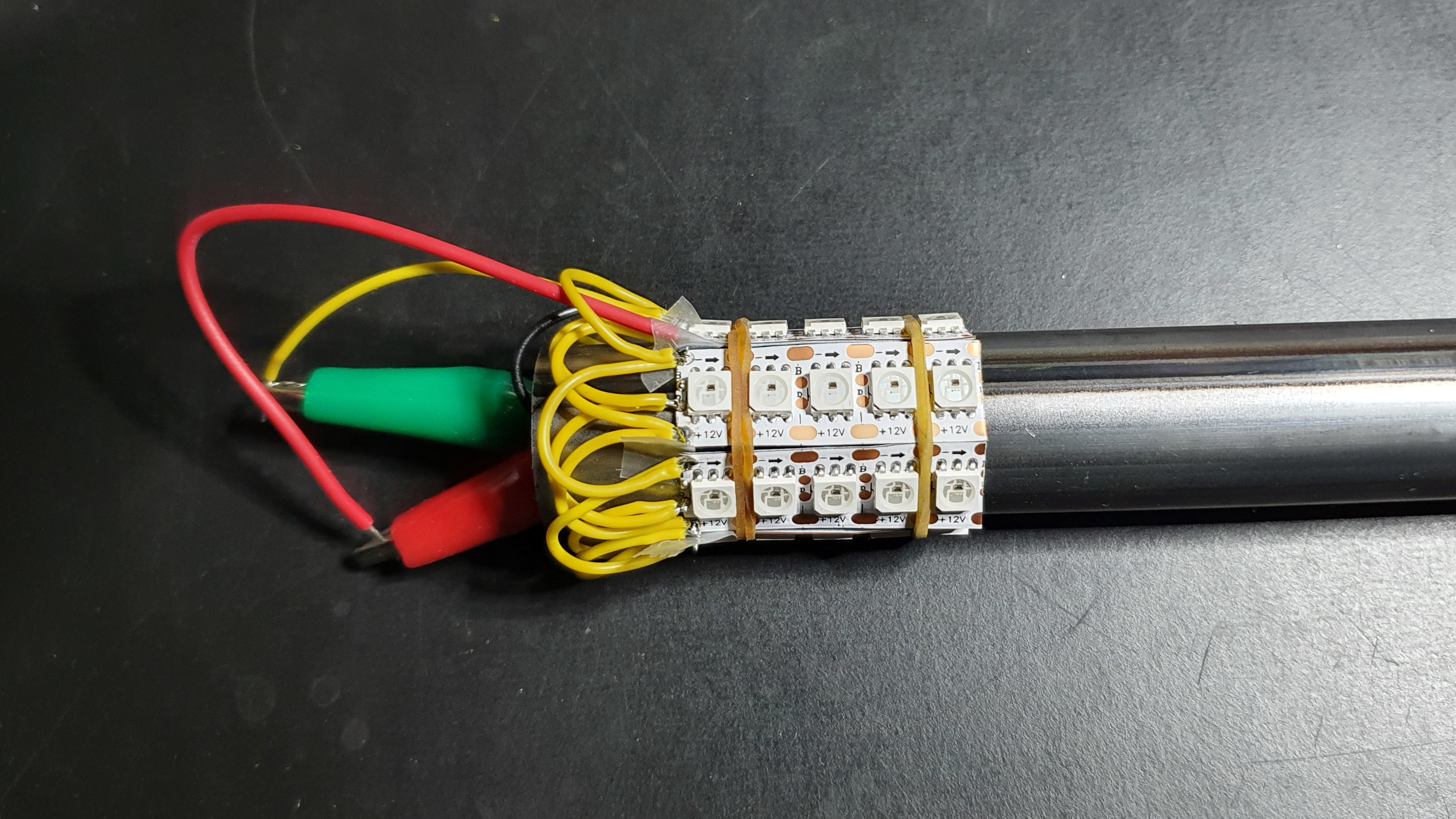
For the light I chose 12V WS2815 with 144 LED’s/m. 12V because I want to reduce the current which the battery’s have to provide and also the heat generated in the cables. “The Hook Up” has a great overview with lot’s of different LED types.
First quick test with the diffuser on. Looking good so far! 😀
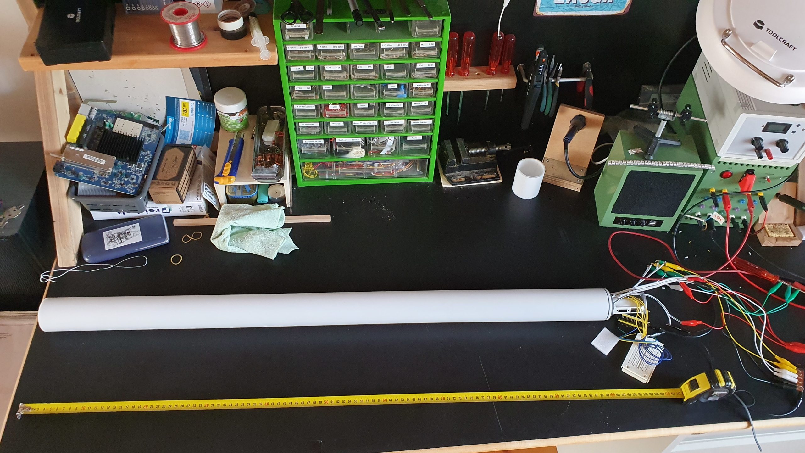
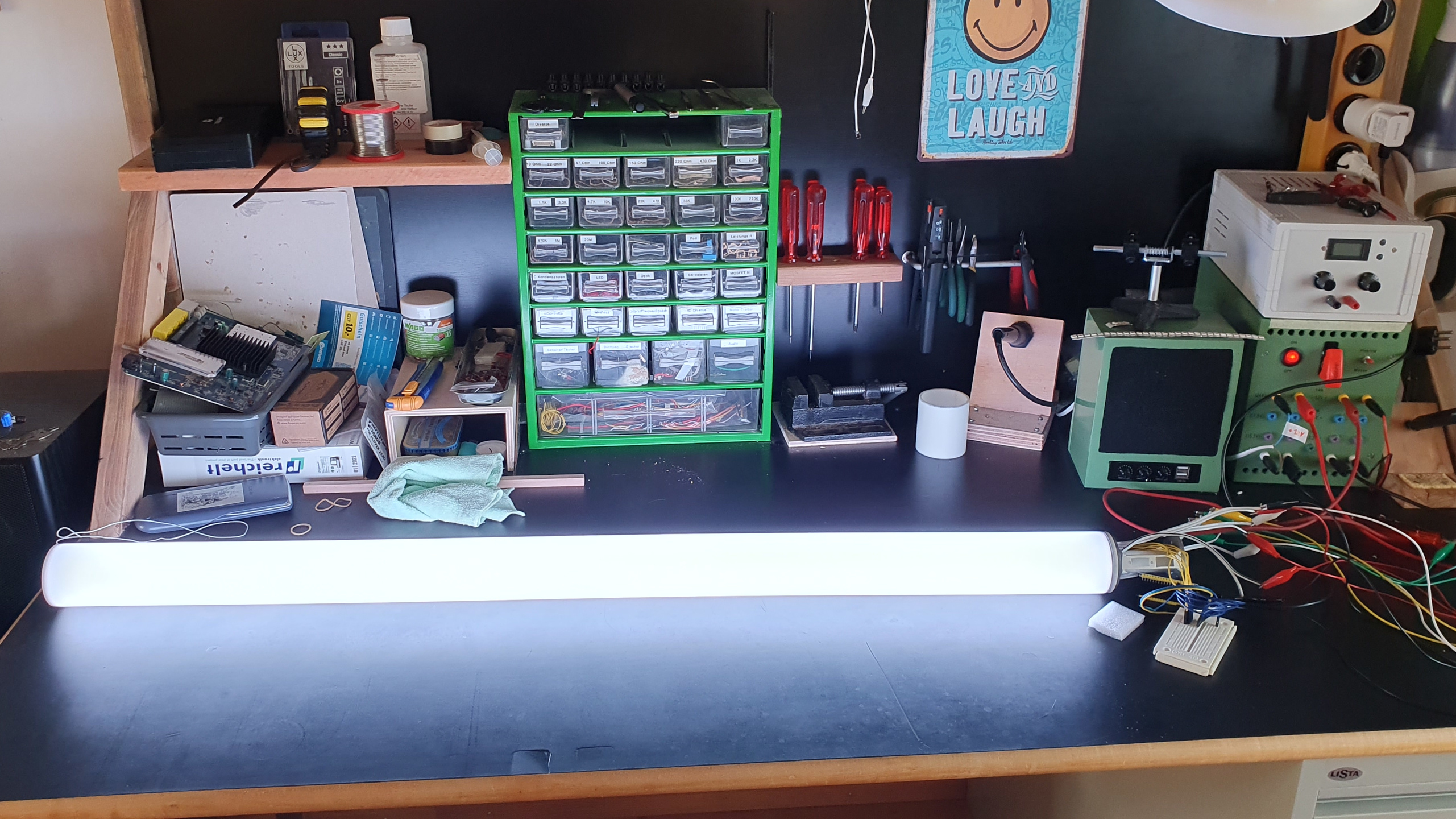
Battery
With an inner diameter of 19.6mm, there was not a lot of room for the battery inside the steel tube, but luckily, the pretty common 18560 cells fit snugly in there. To connect the cells together, I used pieces of bent copper and self-sticking copper foil. I cut a straight channel into a piece of wood which kept the cells perfectly in line during assembly. I also added a bolt and a nut on one end to press the cells gently together.
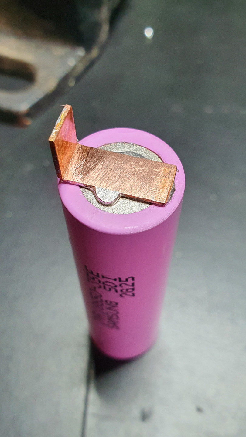
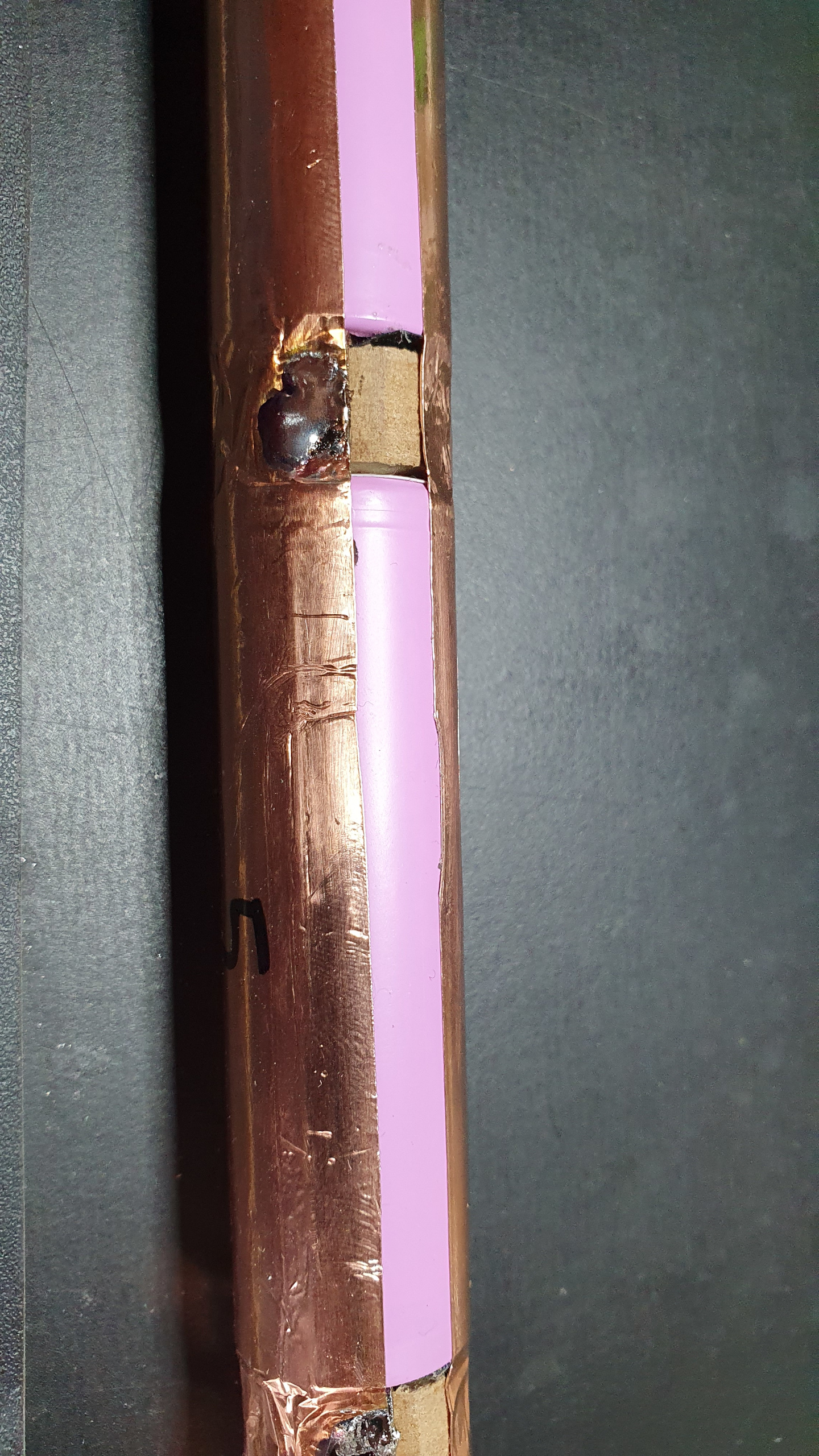
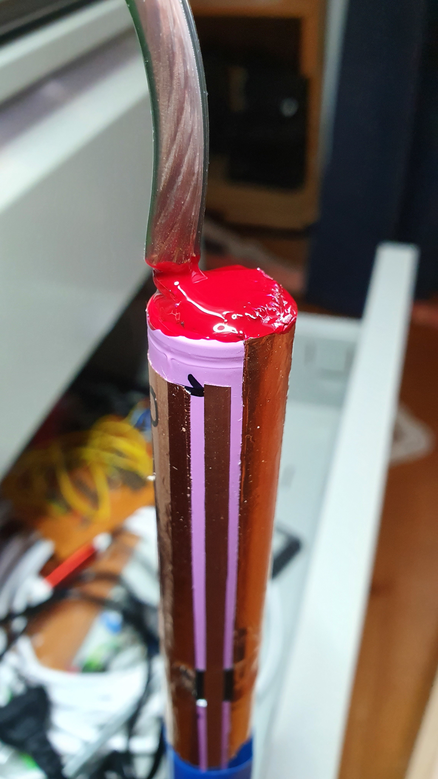
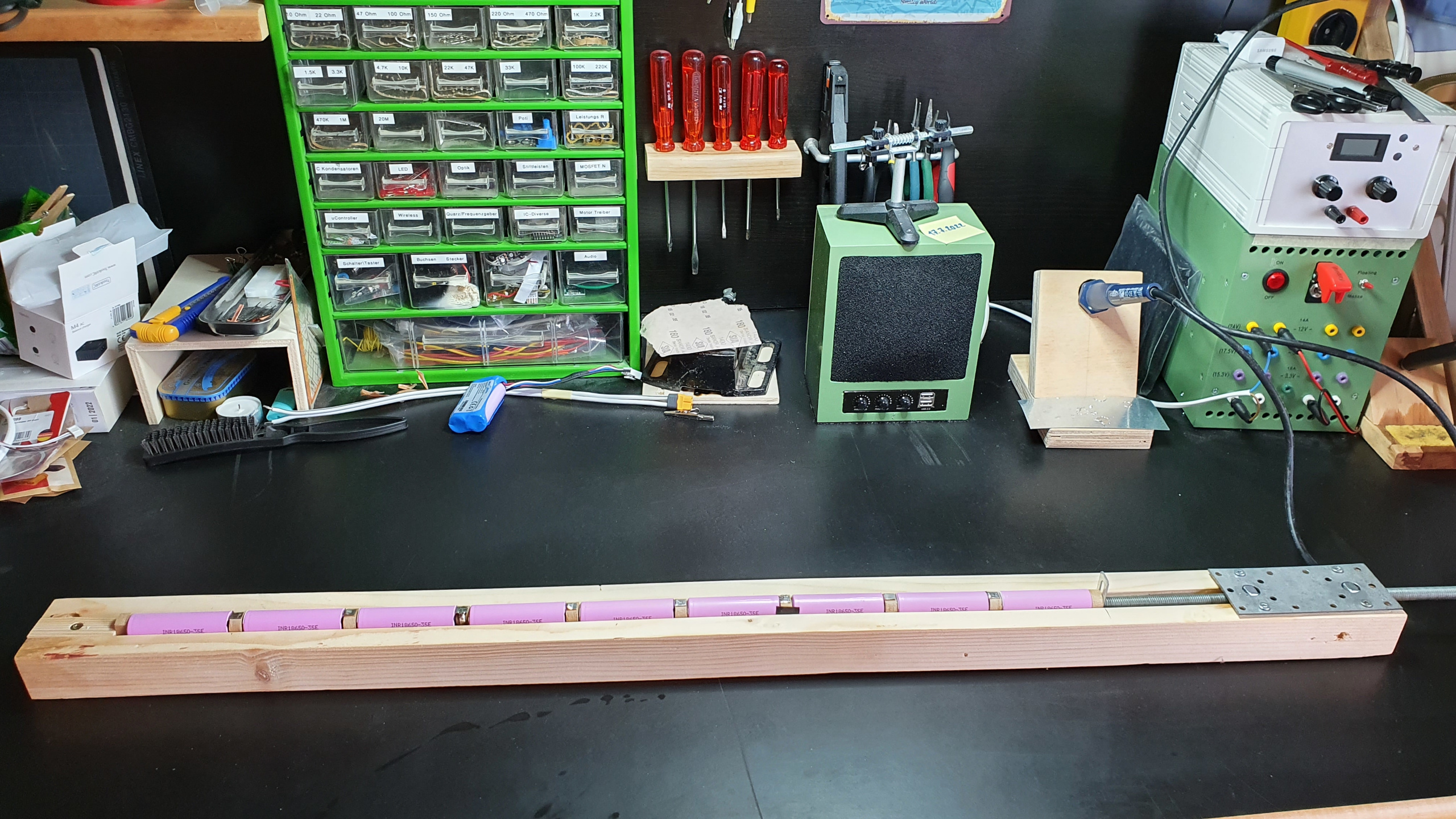
One must be very careful so that the cells do not overheat. A spot welder would be the right tool to connect the cells together, but unfortunately I don’t have one. So I just took a large soldering iron and was careful. The top cell got connected to a 4mm² copper wire an covered with a ton of nail polish for insulation. Then I added a very thin NTC resistor on one of the cells to measure the cell temperature. Finally, the cells were wrapped with two layers of heat shrink tubing.
Caution
Make sure that all the cells have the same voltage before connecting them together! Otherwise, huge currents will flow which can lead to the destruction of the cells!
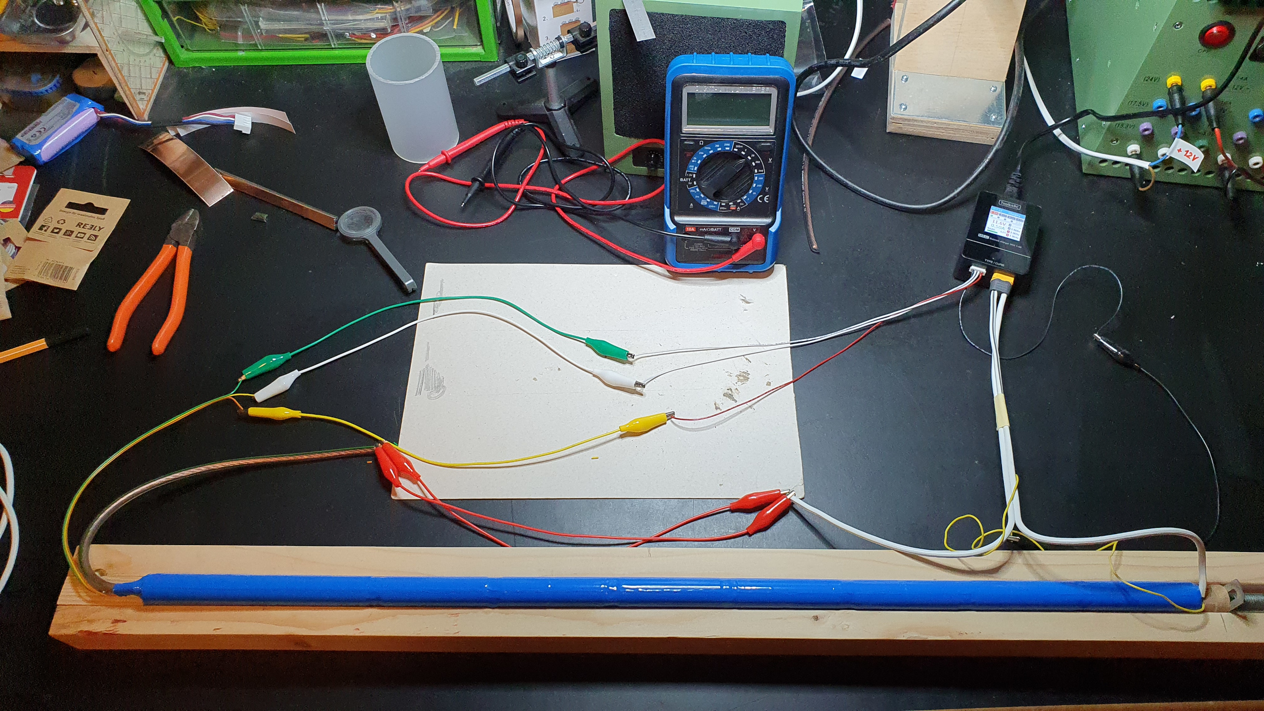
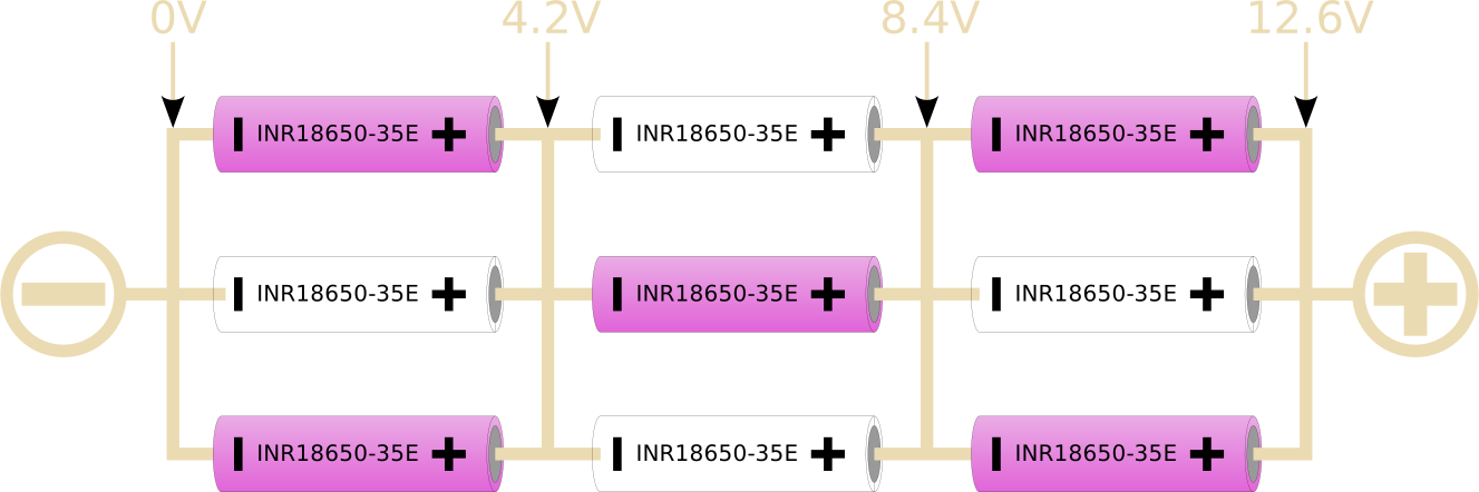
The pack was then charged. I have a 3S3P configuration, so three cells in series and three parallel.
MOSFET's
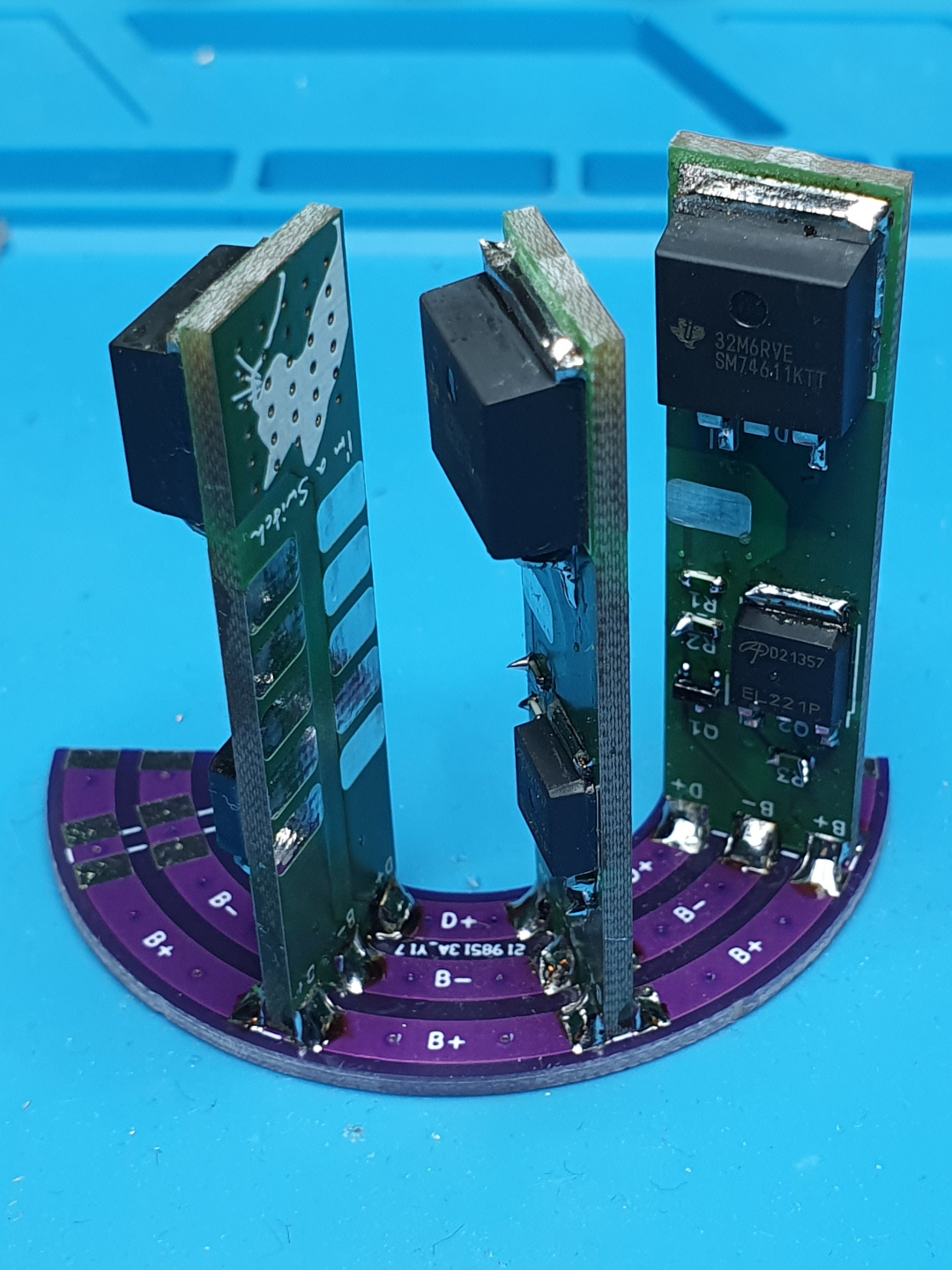
The LED’s draw quite some current, even when turned off. Therefore I added a MOSFET which cuts the power to the LED’s when they are not in use. My first design had some problems. The footprints didn’t match to the schematic symbols which resulted in wrong pin assignment. The MOSFET was also the wrong way around in the schematic and got corrected in the second design.
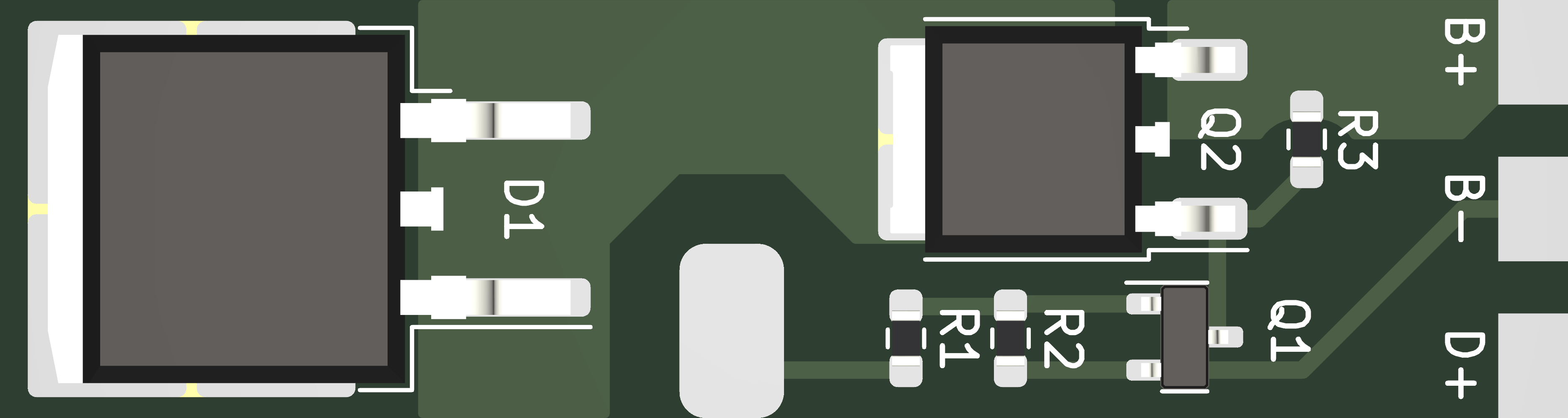

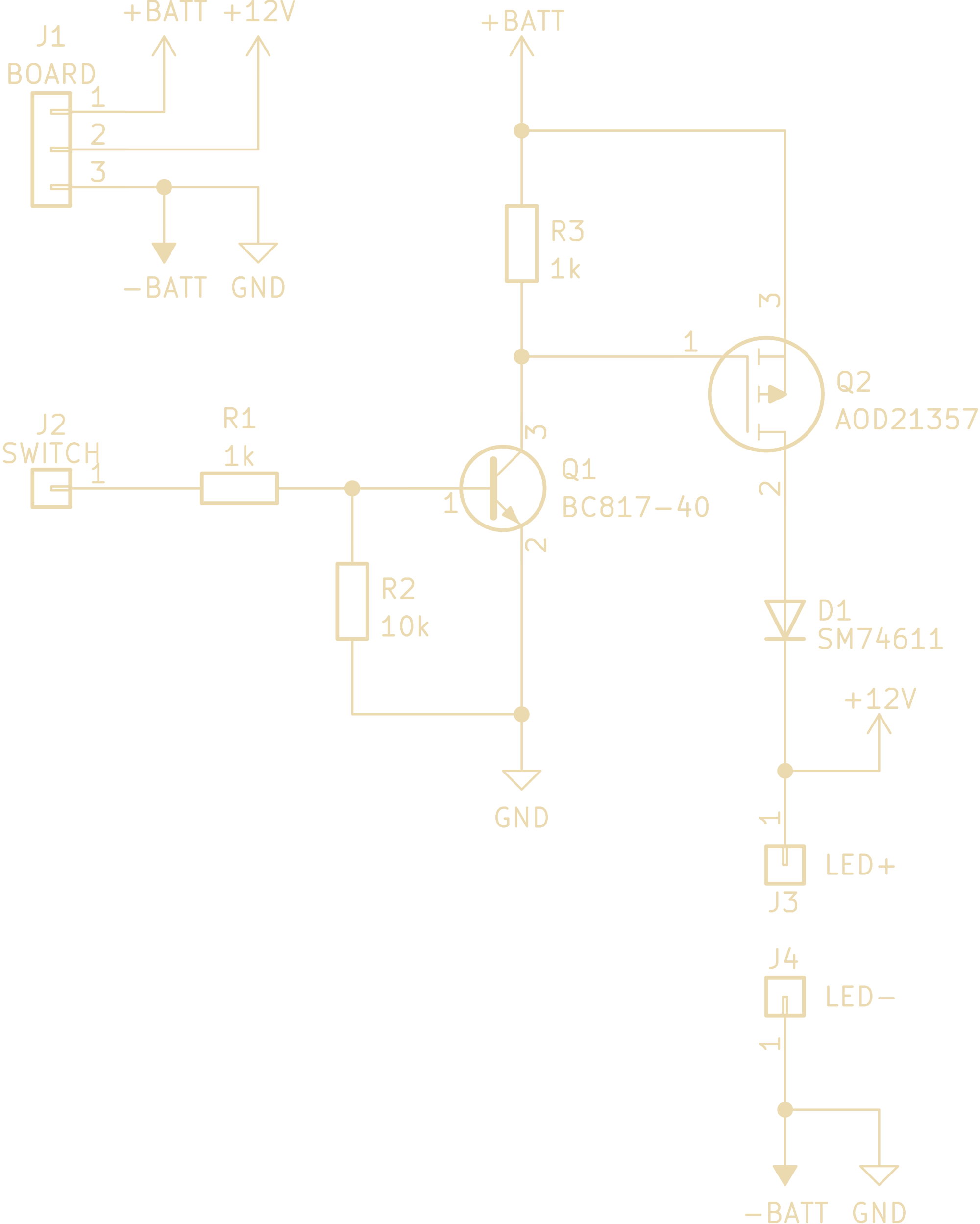
The PCB’s where then soldered to another PCB which distributes the power. Then the where mounted on the LED-Tube with double sided adhesive tape.
Controller
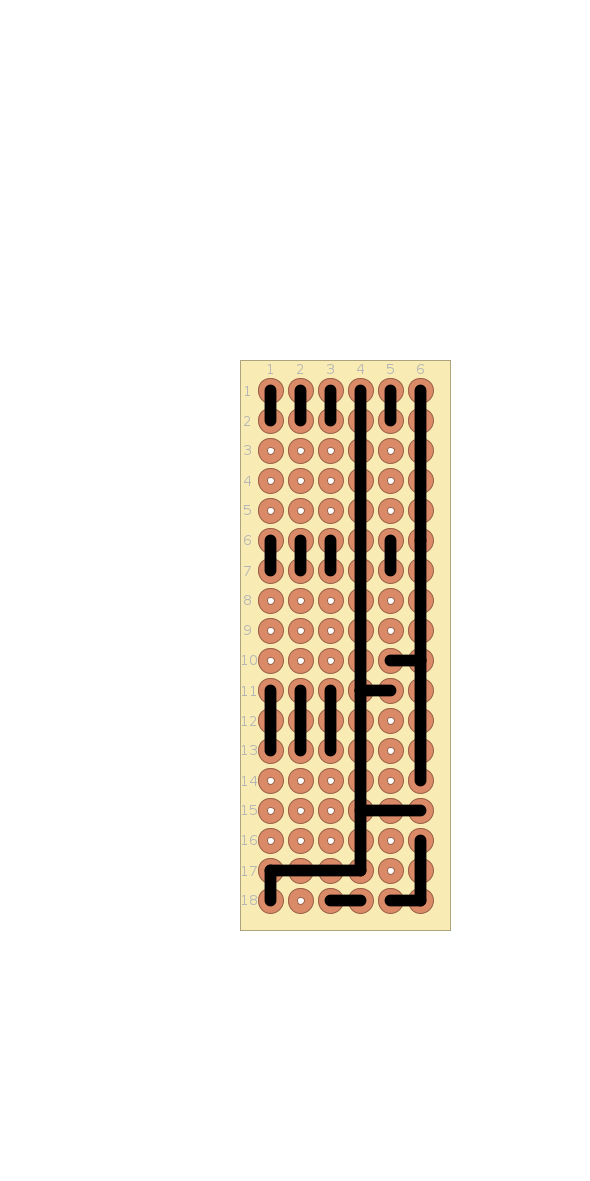
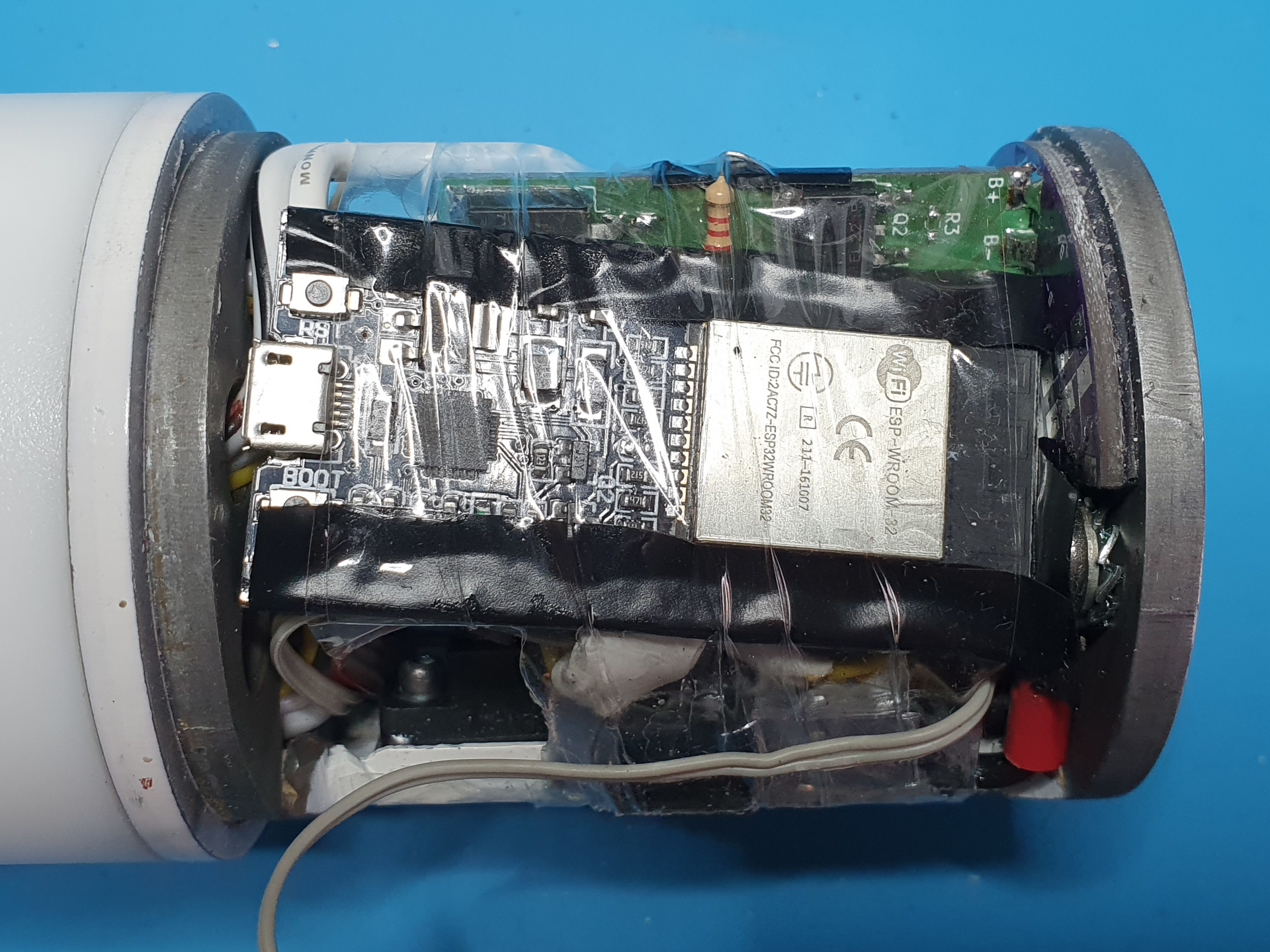
To control the LED’s and measure the battery temperature and voltage I used a ESP32 microcontroller. I also made a little voltage-divider board where the battery voltages get broken down to microcontroller friendly levels.
Download vdivider_board.pdf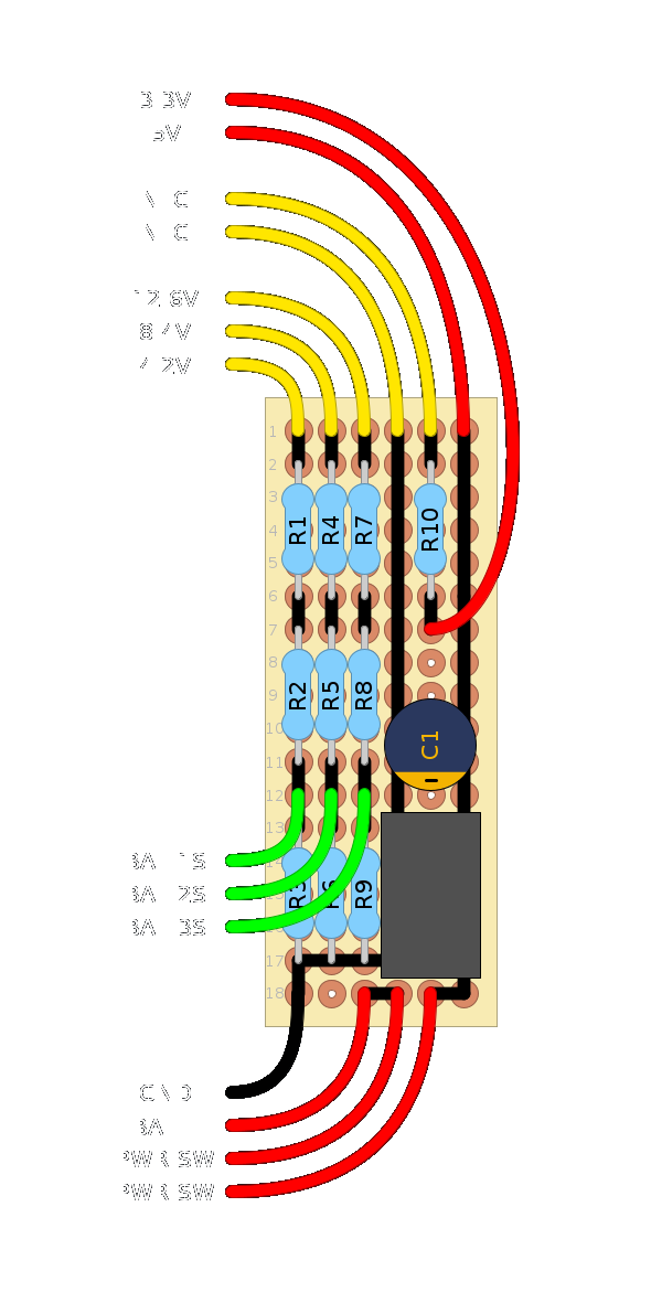
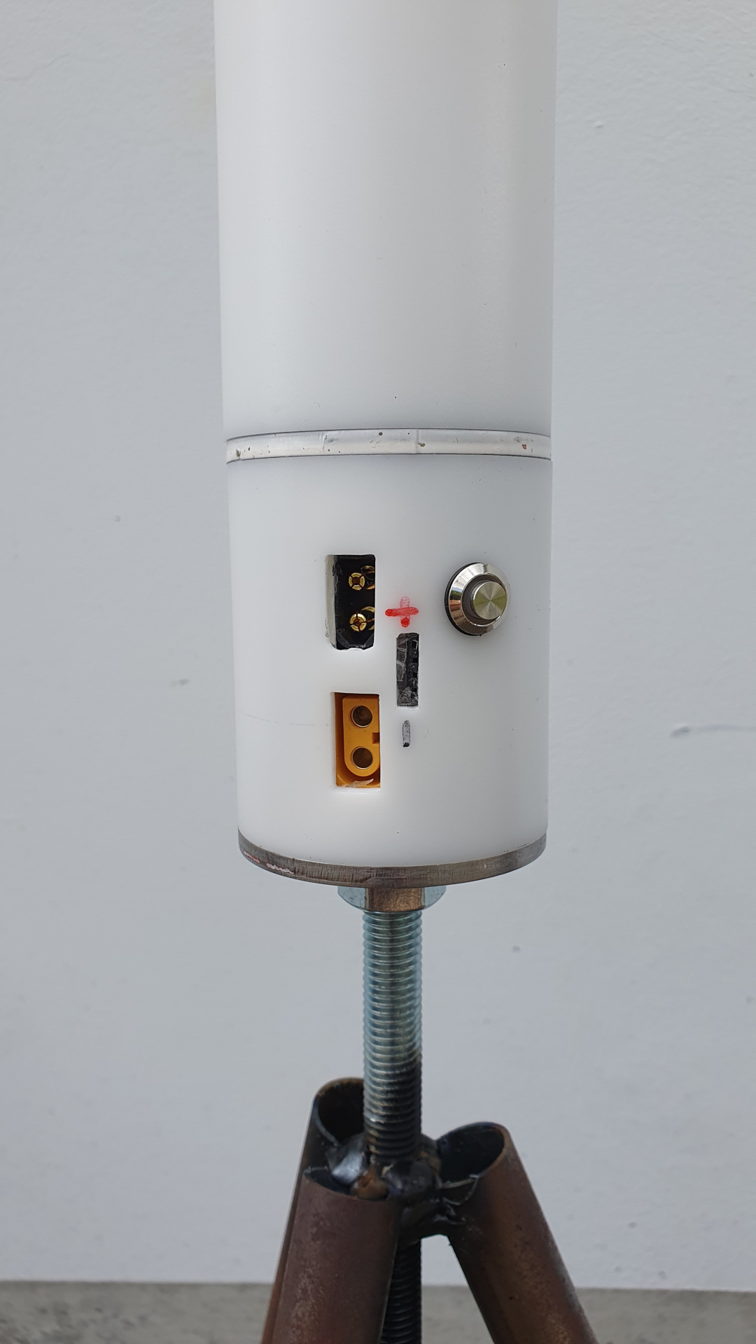
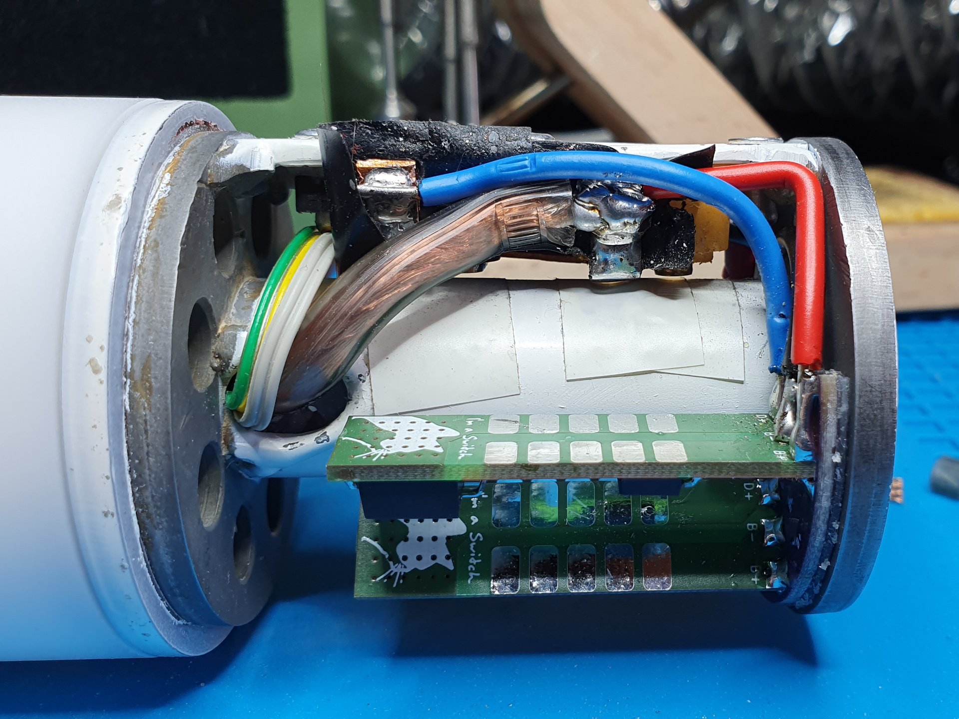
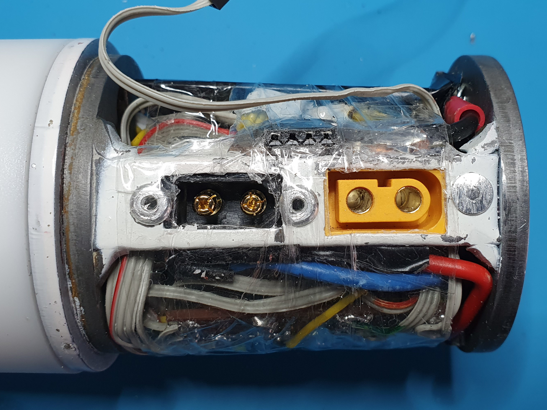
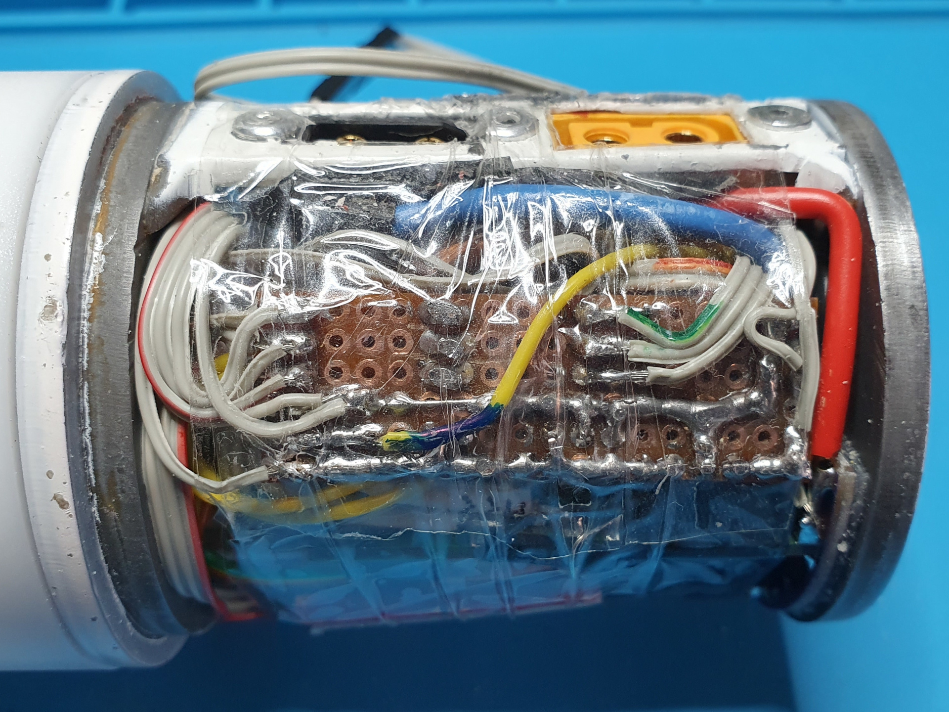
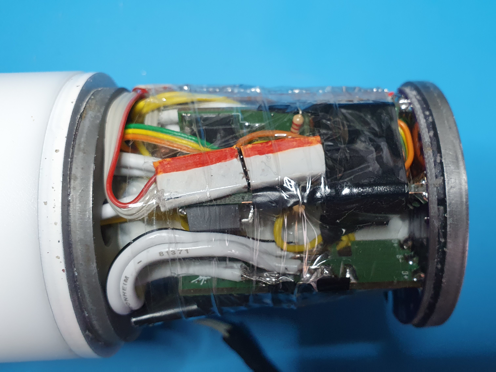
Everything was then soldered together and stuffed in to the tube. It fits just barely... but it fits. 🙂
Software
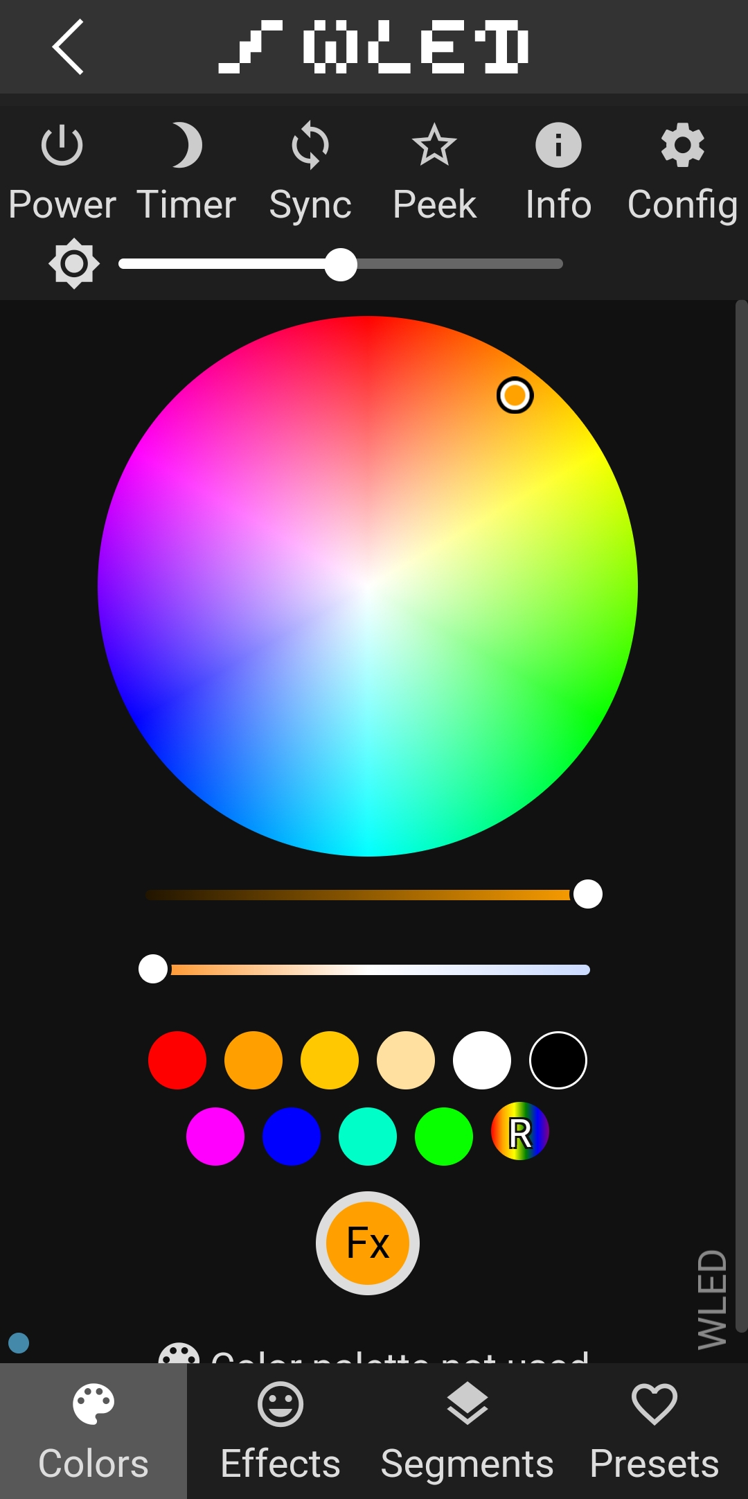
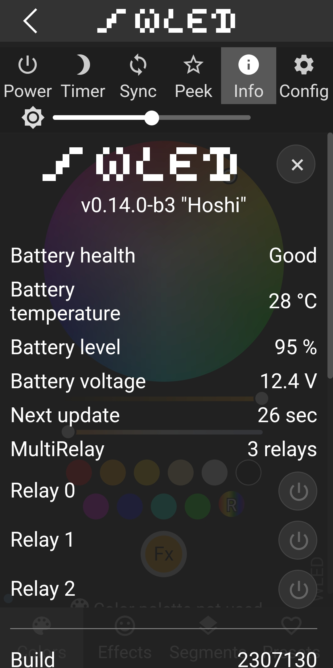
I used WLED to control and manage everything. It is very capable, can be controlled in so many ways and has a variety of predefined animations. I had to compile it my self as I used the usermods “multi_relay” and “Battery” and also a little usermod I made my self to monitor the temperature of the battery. I really like the OTA feature as I don’t have to take apart the LED-Tube to upload a update to the ESP32. It’s a awesome project and everyone who worked on it did a really nice job!
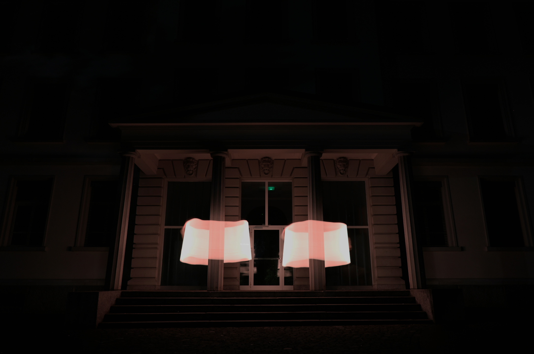
Photos